双二阶滤波器原理
双二阶滤波器说明
双二阶滤波器(biquad)是最常用的滤波器之一。双二阶滤波器是双二阶(两个极点和两个零点)的IIR滤波器。考虑到更高阶数的滤波器对系数敏感,双二阶可以单独使用,或者在更复杂的滤波器中作为基本的构建单元。例如,一个双二阶低通滤波器有12dB/octave斜度的截止频点,可以用于音调控制;如果需要一个24dB/octave的斜度,可以级联两个双二阶滤波器,这个结构比一个单4阶滤波器对参数更不敏感。
双二阶滤波器有几种不同的结构。最直观也最直接的实现是用一个二阶差分方程( (y[n] = a0*x[n] + a1*x[n-1] + a2*x[n-2] – b1*y[n-1] – b2*y[n-2])),称之为Direct Form I:
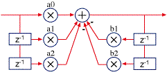
Direct Form I
在定点(没有浮点数)处理器中,Direct Form I是最好实现的,因为只有一个加法点(定点DSP一般都有扩展的累加器,可以在运算中有一定的溢出)。
我们可以把Direct Form I在加法那个点分成两部分,如下图:
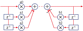
然后,我们把分开的两部分交换顺序,让反馈的部分(极点)先计算:
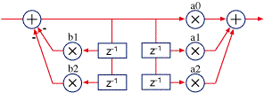
可以看到,上图中成对的Z延时是有冗余的,剔除冗余后得到Direct Form II:
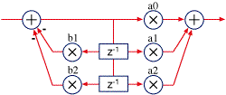
Direct Form II
Direct Form II更适合浮点处理器,节省了存储空间,并且浮点处理器不会有溢出问题(不像定点处理器有溢出问题)。我们可以通过转置来进一步改进Direct Form II. 把信号的流向前后颠倒,输出变成输入,分支节点变成加法,加法变成分支节点。通过转置,滤波器的特征不变,并且,转置后更有利于用浮点来计算。当相加的两个数比较临近时,浮点数会有更高的精度(把很小的数加到一个很大的数上,精度会比两个相近的数相加有更低的精度)。下图是转置后的Direct Form II( Transposed Direct Form II):
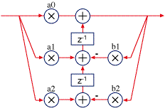
Transposed direct form II
补充说明和一些建议
总结,direct form I更适合定点计算,转置(transposed) Direct form II更适合浮点计算。
量化误差,在低频情况下,容易导致双二阶滤波器更脆弱(不稳定),主要是因为反馈系数(b1和b2)以及中间值(the delay memory)。精度不够,会导致不容易精确控制极点的位置,尤其在极点靠近单位圆的情况下,因此,量化误差会变成一个重要问题。第二个问题,是关于中间值的,相乘之后会产生更多的位,当保存下来时,需要做截断处理。这个误差反馈回滤波器系统,可能导致系统不稳定。32位浮点数对于音频滤波器来讲一般是足够好了。但是,对于很低频率(如控制类信号的滤波)和高采样率情况下,可能需要双精度才行。
对于定点实现的滤波器,24位的系数和中间存储,基本上可以很好的满足需要了,但是48k采样率下从300Hz往下(或者96k采样率下从600Hz往下),就开始变得不稳定了。定点处理器上实现双精度开销很大,幸好,有一个简单的方法可以提高稳定度。看看Direct Form I的结构图,把高精度的累加结果保存在低精度的中间存储器中,这个过程会造成精度损失。把精度损失(量化损失:高精度计算结果与低精度存储之间的差值)加回到下一次输出结果的计算中,近似达到双精度,当然,会增加一些运算量。这个技巧被称为First Order Noise Shaping. 有更高阶的Noise Shapers,但是First Order已经足够好了,可以应付所有音频需要,即使在高采样率的情况下。
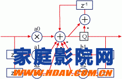
Direct Form I with first-order noise shaping
没有双精度的系数和计算,仅仅用16位定点,通常情况下,是不适合用于处理音频的。
最后,双二阶滤波器仅仅是DSP工具之一,它也不全是最好的滤波器。还有其它的滤波器没有低频敏感问题的(通常,双二阶滤波器对于高频是有比较好精度的,对于低频则不太好;有其它类型的滤波器,精度的分布更均匀,或者可以牺牲部分高频的精度来换取低频的精度)。然而,双二阶滤波器很通用和普遍,设计工具也很充足,所以,双二阶滤波器会是首选,除非有明确的原因需要用其它类型的滤波器。
有太多滤波器类型了,另外一个对synthesizer来说很经常使用的是state variable filter。对于低频有很好的性能,对于高频有一些需要绕过的限制,但是,最重要的是频率和Q系数是分开的,且很容易改变。它也构成了低频sine波产生器。
三种滤波器类型的计算过程(系数如何使用)
归一化公式如下:
H(z)=b0+b1z−1+b2z−21+a1z−1+a2z−2H(z)=b0+b1z−1+b2z−21+a1z−1+a2z−2
系数为 b0b0, b1b1and b2b2和 a1a1, a2a2
Direct Form I 的计算过程
y[n]=b0x[n]+b1x[n−1]+b2x[n−2]−a1y[n−1]−a2y[n−2]y[n]=b0x[n]+b1x[n−1]+b2x[n−2]−a1y[n−1]−a2y[n−2]
Direct Form II 的计算过程
y[n]=b0w[n]+b1w[n−1]+b2w[n−2]y[n]=b0w[n]+b1w[n−1]+b2w[n−2]
where
w[n]=x[n]−a1w[n−1]−a2w[n−2]w[n]=x[n]−a1w[n−1]−a2w[n−2]
Transposed direct forms
y[n]=b0x[n]+s1[n−1]y[n]=b0x[n]+s1[n−1]
where
s1[n]=s2[n−1]+b1x[n]−a1y[n]s1[n]=s2[n−1]+b1x[n]−a1y[n]
and
s2[n]=b2x[n]−a2y[n]s2[n]=b2x[n]−a2y[n]
附录:英文原文
第一个链接来源的英文原文
One of the most-used filter forms is the biquad. A biquad is a second order (two poles and two zeros) IIR filter. It is high enough order to be useful on its own, and—because of coefficient sensitivities in higher order filters—the biquad is often used as the basic building block for more complex filters. For instance, a biquad lowpass filter has a cutoff slope of 12 dB/octave, useful for tone controls; if you need a 24 dB/octave slope, you can cascade two biquads, and it will have less coefficient-sensitivity problems than a single fourth-order design.
Biquads come in several forms. The most obvious, a direct implementation of the second order difference equation (y[n] = a0*x[n] + a1*x[n-1] + a2*x[n-2] – b1*y[n-1] – b2*y[n-2]), called direct form I:

Direct form I
Direct form I is the best choice for implementation in a fixed point processor because it has a single summation point (fixed point DSPs usually have an extended accumulator that allows for intermediate overflows).
We can take direct form I and split it at the summation point like this:

We then take the two halves and swap them, so that the feedback half (the poles) comes first:

Now, notice that one pair of the z delays is redundant, storing the same information as the other. So, we can merge the two pairs, yielding the direct form II configuration:

Direct form II
In floating point, direct form II is better because it saves two memory locations, and floating point is not sensitive to overflow in the way fixed point math is. We can improve this a little by transposing the filter. To transpose a filter, reverse the signal flow direction—output becomes input, distribution nodes become summers, and summers become nodes. The characteristics of the filter are unchanged, but in this case it happens that the floating point characteristics are a little better. Floating point has better accuracy when intermediate sums are with closer values (adding small numbers to large number in floating point is less precise than with similar values). Here is the transposed direct form II:

Transposed direct form II
Notes and recommendations
Again, direct form I is usually the best choice for fixed point, and transposed direct form II for floating point.
At low frequency settings, biquads are more susceptible to quantization error, mainly from the feedback coefficients (b1 and b2) and the delay memory. Lack of resolution in the coefficients makes precise positioning of the poles difficult, which is particularly a problem when the poles are positioned near the unit circle. The second problem, delay memory, is because multiplication generates more bits, and the bits are truncated when stored to memory. This quantization error is fed back in the filter, causing instability. 32-bit floating point is usually good enough for audio filters, but you may need to use double precision, especially at very low frequencies (for control filtering) and at high sample rates.
For fixed point filters, 24-bit coefficients and memory work well for most filters, but start to become unstable below about 300 Hz at 48 kHz sample rate (or twice that at 96 kHz). Double precision is always costly on a fixed point processor, but fortunately there is a simple technique for improving stability. Looking at the direct form I drawing, the quantization occurs when the higher precision accumulator is stored in the lower precision delay memory on the right side. By taking the quantization error (the difference between the full accumulated value and its value after storing it to memory) and adding it back in for the next sample calculation, the filter performs nearly as well as using full double precision calculations, but at a much lower computational cost. This technique is called first order noise shaping. There are higher order noise shapers, but this one works well enough to handle almost all audio needs, even at high sample rates.

Direct form I with first-order noise shaping
In general, 16-bit fixed point processing is not suitable for audio without double precision coefficients and computation.
Finally, biquads are just one of a DSP programmers tools—they aren’t always the best filter form. There are other filters that don’t share the biquad’s low-frequency sensitivities (in general, biquad coefficient precision is very good at high frequencies, and poor at low ones; there are other filter forms that spread the precision out more evenly, or trade off reduced high frequency performance for better low frequency performance). However, biquads are well known and design tools are plentiful, so they are usually the first choice for an IIR filter unless you find a reason to use another.
There are too many filter forms to cover, but one other filter form that is popular for synthesizers is the state variable filter. It has very excellent low frequency performance, and limitations in the high frequencies that have to be worked around, but most importantly frequency and Q coefficients are separate and easy to change for dynamic filtering. It also make a great low frequency sine wave generator.
第二个链接来源的英文原文
In signal processing, a digital biquad filter is a second-order recursive linear filter, containing two poles and two zeros. “Biquad” is an abbreviation of “biquadratic”, which refers to the fact that in the Z domain, its transfer function is the ratio of two quadratic functions:
H(z)=b0+b1z−1+b2z−2a0+a1z−1+a2z−2H(z)=b0+b1z−1+b2z−2a0+a1z−1+a2z−2
The coefficients are often normalized such that a0 = 1:
H(z)=b0+b1z−1+b2z−21+a1z−1+a2z−2H(z)=b0+b1z−1+b2z−21+a1z−1+a2z−2
High-order IIR filters can be highly sensitive to quantization of their coefficients, and can easily become unstable. This is much less of a problem with first and second-order filters; therefore, higher-order filters are typically implemented as serially-cascaded biquad sections (and a first-order filter if necessary). The two poles of the biquad filter must be inside the unit circle for it to be stable. In general, this is true for all filters i.e. all poles must be inside the unit circle for the filter to be stable.
Implementation
Direct form 1
The most straightforward implementation is the direct form 1, which has the following difference equation:
y[n]=1a0(b0x[n]+b1x[n−1]+b2x[n−2]−a1y[n−1]−a2y[n−2])y[n]=1a0(b0x[n]+b1x[n−1]+b2x[n−2]−a1y[n−1]−a2y[n−2])
or, if normalized:
y[n]=b0x[n]+b1x[n−1]+b2x[n−2]−a1y[n−1]−a2y[n−2]y[n]=b0x[n]+b1x[n−1]+b2x[n−2]−a1y[n−1]−a2y[n−2]
Here the b0b0, b1b1and b2b2coefficients determine zeros, and a1a1, a2a2 determine the position of the poles.
Flow graph of biquad filter in direct form 1:
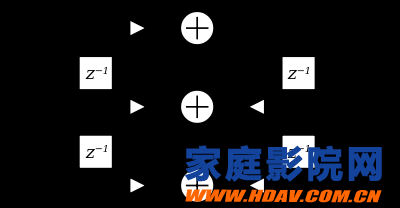
Biquad filter DF-I.svg
Direct form 2
The direct form 1 implementation requires four delay registers. An equivalent circuit is the direct form 2 implementation, which requires only two delay registers:
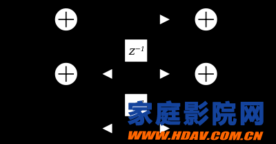
The direct form 2 implementation is called the canonical form, because it uses the minimal amount of delays, adders and multipliers, yielding in the same transfer function as the direct form 1 implementation. The difference equations for direct form 2 are:
y[n]=b0w[n]+b1w[n−1]+b2w[n−2]y[n]=b0w[n]+b1w[n−1]+b2w[n−2]
where
w[n]=x[n]−a1w[n−1]−a2w[n−2]w[n]=x[n]−a1w[n−1]−a2w[n−2]
Transposed direct forms
Each of the two direct forms may be transposed by reversing the flow graph without altering the transfer function. Branch points are changed to summers and summers are changed to branch points.[1] These provide modified implementations that accomplish the same transfer function which can be mathematically significant in a real-world implementation where precision may be lost in state storage.
The difference equations for Transposed Direct Form 2 are:
y[n]=b0x[n]+s1[n−1]y[n]=b0x[n]+s1[n−1]
where
s1[n]=s2[n−1]+b1x[n]−a1y[n]s1[n]=s2[n−1]+b1x[n]−a1y[n]
and
s2[n]=b2x[n]−a2y[n]
本文翻译自:http://www.earlevel.com/main/2003/02/28/biquads/和wiki: https://en.wikipedia.org/wiki/Digital_biquad_filter(英文原文附在最后面)

注:本文转载自admin,目的在于分享信息,不代表本站赞同其观点和对其真实性负责,如有侵权请联系我们及时删除。

